
125 Pixel Adalight / Ambibox Ambilight
Fun with Addressable LEDs
| Part | Cost |
|---|---|
| WS2801 Addressable RGB LED Pixels | $75 |
| Arduino Uno | $25 |
| Beefy 5v Power Supply | $20 |
| 3/4" PVC Pipe and 4 Elbow Fittings | $10 |
| Drill and a 1/2" bit | |
| Velcro Wire Wraps or Zip Ties | |
| TOTAL | ~ $130 |
I bumped in to a video of an adalight setup a couple of years ago and started planning to add one some day. The name comes from Adafruit’s DIY approach to a line of TVs from Phillips which included the ‘Phillips Ambilight‘ feature. They put arrays of LEDs around the back side of the screen to produce an ambient glow that followed the colors on the screen.
The idea was twofold: First, high end home theater designers will often recommend your screen be set forward from a wall by a foot or two, and that it be subtly back lit. It fairly dramatically increases your perception of contrast and depth in the image and it can relieve eyestrain on long movies. Second, since you are focused on the center of the screen, and your peripheral vision is fairly low resolution, you don’t need more detail than a moving glow around the edges of the screen to make it feel much larger than it is.
Of course I would add that individually addressable RGB LEDs are a ton of fun to play with, and almost any excuse to build things with them is a good excuse.
When we moved and my old screen wouldn’t fit down the stairs in the new house, it was a great opportunity to re-design it to float out off of the wall to make room for lights all the way around.
Now that it is winter again, a cold snap trapped me inside long enough to finally get around to setting this thing up. The effect is absolutely fantastic. I worried that it might be distracting and gaudy, but I have been very pleasantly surprised.
You’ll find that this turned out to have a lot rehashing of the Adalight writeup over at Adafruit, but I always like to read a few people’s experiences before ordering a bunch of hardware, so I thought I would write it up anyway. I wont bother to cover the wiring, since they cover it well.
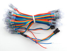
LED Pixels
There are a lot of options here. Several controller chips and two main form factors: bullet style with wires like I used, and flexible plastic strips with LEDs affixed. The key features are that the pixels must be be able to produce red, green, and blue (RGB), and they must be individually addressable. You can google around for Arduino, Adalight, and the chips you are looking at buying and see if anyone has already made a library that works, or you can write your own. Last year, some waterproof bullet style WS2801 RGB pixels for this project occurred to me as a Christmas idea, and my inlaws (who are starting to get used to me asking for that sort of thing for Christmas) very generously bought me several strings.
These pixels are somewhat sensitive to signal noise, so try not to run them long distances parallel to AC current. More importantly though, they absolutely depend on proper grounding. If your lights are behaving strangely, make sure the ground on your arduino, your leds, and your power supply are all securely connected together, and that they are actually grounded.
When I got the system wired up, the first half of the LEDs looked great, the second half was dead. After much fiddling, I discovered that the gender of the little connectors on either end of the strands of lights varied between strands. These LED strands do have an input and an output end, and I ended up having to cut the connectors off of two strands and swap them end for end before they would all work together.
The last little hiccup I bumped in to was that I had two pixels at the top of the screen that flickered erratically, especially when only dimly lit, and the last third or so of the LEDs in the loop would occasionally flicker and strobe together as well. I suspected noise on the data wire at first, so I checked all my grounds and went to some trouble to shorten slack in the wire and such, without effect. Finally I gave up and spliced out those two bad pixels at the top with some from a spare strand. That fixed everything. Each pixel along the strand finds its own instructions in the data stream and then passes the rest on down the line, apparently one of those two was malfunctioning and occasionally garbling the data for later pixels as well.
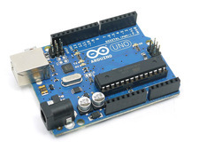
Arduino Uno
Actually, most of the newer arduinos will do, this is just the one I am using for now.
There are several ways people have approached this, and I tried several out before settling on this one for now. Here are the basics: Software on your computer captures images from the screen, takes color samples from zones around the outside of the screen and feeds that data to the arduino over usb using the protocol Adafruit designed for their adalight arduino sketch. The adalight sketch on the arduino takes that data and streams it to the pixel’s controller chips over the data and clock leads in the pixel string. The individual controller chips switch current through their individual LEDs accross the positive and ground wires on the strand. Its important to note that the arduino is not powering the LEDs, it is just sending instructions to the chips at each pixel. The power for the LEDs comes through the positive and ground leads in the LED string, and is switched by the controller chips.
Adafruit’s Adalight sketch has become something of a standard out there for software on the arduino. They also produced a sketch for Arduino’s Processing package that runs on the computer and does the screen grabbing, but it is really just a proof of concept and it is terribly slow (10ish frames per second on my i7). Fortunately, there are several other great, free options for the computer part of the job. I tried several and settled on Ambibox for several of its features. I am a bit of a stickler for color accuracy, and Ambibox provides some great controls for things like overall hue and gamma correction for the string as a whole and then for each individual pixel.
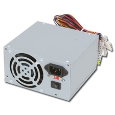
Power Supply
These LEDs are a bit power hungry. You’ll need 5 volts in the neighborhood of 4 amps per hundred pixels. There are plenty of LED driver power supplies on ebay that are cheap and would do the job. I used an old ATX computer power supply I had laying around since it had a 12v rail for the arduino, and a 5v rail for the LEDs, all at many times the amperage I need in a clean, cool, cheap, reliable unit.
One quirk of these strands is that the power wires can’t reliably carry the current required for more than maybe 50 pixels. I ran some 12 gauge zip cord I had to every other junction between strands (50 pixels apart) and connected it to the power supply to provide a heartier bus for the current.
PVC Pipe Frame
I used 30 feet of 3/4 PVC pipe, and 4 elbow fittings to build the frame. It could not have worked better. Rigid enough to be stable, flexible enough to fit the curve of the screen, and it couldn’t be easier to work with… All for the price of a latte.
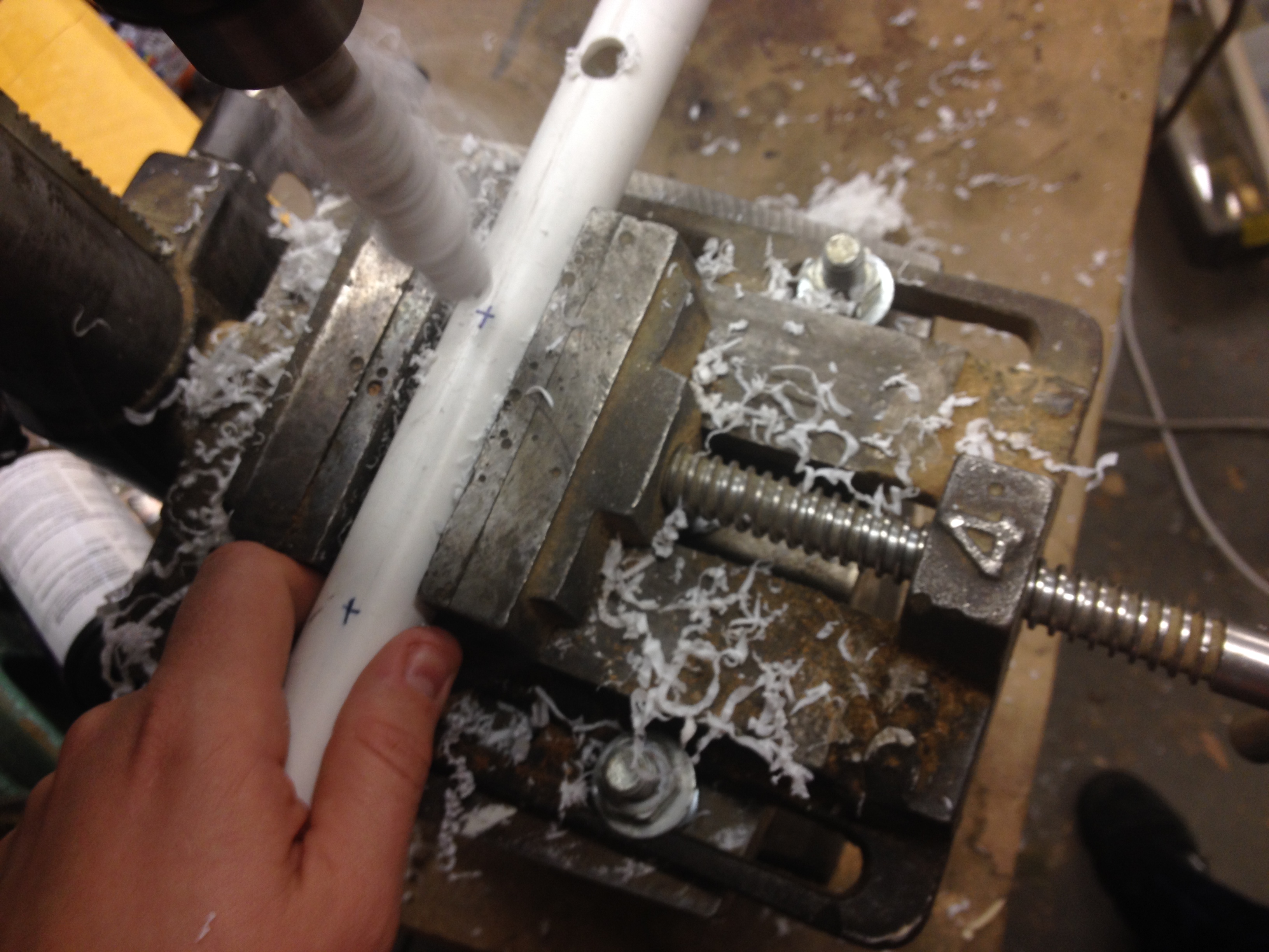
My little helper and I got out our measuring tapes and markers (his washable, mine permanent), and marked the pipes every 3 inches. Keep in mind that you’ll need your series of holes to be centered on the length of pipe for each side. You may want to start in the middle of the length of the pipe and work your way out. The PVC they had at the local big box store had a stripe painted down the length that gave us a nice straight line to work with for the lengthwise axis. If the pipe you can get locally doesn’t happen to, I imagine a chalk line would do the job.

I set up the vice on the drill press with the jaws just loose enough to let the pipe slide through. My little helper stood on the bench and ran the feed lever and I moved the pipe between each hole. We used a half inch bit and drilled all the way through both sides of the pipe, which made a hole that the lights fit perfectly in. Just tight enough to hold the lights firmly, but loose enough that I can get them in and out without risk of damaging them if I need to.
I attached the pipe to the back of the screen frame with duct strapping, pushed it together with the elbow fittings, and inserted all of the lights. One day soon I’ll have to get a wall or something up behind the screen and then go to some trouble to really dial in the color balance.
Leave a comment or send me an email if you have any questions, I’ll be happy to try to help!
Leave a Reply