
Multiplayer Game Pad – Stomp Directional Pads
Step/Stomp Pressure Directional Game Pad Switches.
Some Background
The local makerspace signed up to make a multiplayer ‘snake’ game for our regional mini maker faire. You know the one where the snake grows a bit each time it eats and apple, and you can’t let it bit the walls or its own tail? I’ve wanted an excuse to tinker with making a DDR pad for my wife, she always liked that game, so I signed up to make the stomp switches to see how it went!
I dug through a ton of stuff in the internet about building DDR pads. Most of it was from quite a while back. I forget it’s been a while since those were ‘in’. Acrylic is pretty widely used because it’s tough, easy to light in cool ways, and flexible enough to give a bit to close the switch contacts.
I settled on an approach where you start with two sheets of galvanized flashing that are held apart by thin weatherstripping around the edges. They form the contacts for the switch. The bottom sheet is glued to the wood base with contact cement, the top sheet is glued to a sheet of acrylic. You sandwich some weatherstripping between those and add a third layer of acrylic on top for a replaceable stomp surface. Usually the top layer of acrylic is clear, and you put your artwork under it.
This whole stack was most often held together and in place one of two ways, either diagonal clamps over the corners of the pad, or by drilling screw holes in the stack and screwing it down. Often the screw is sleeved with rubber hose of some kind to help keep from fracturing the acrylic if/when the pad takes a less-than-straight-down kicking. I went with the screws method, I thought it looked nicer for this particular project.
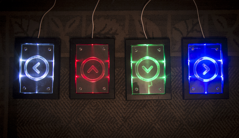
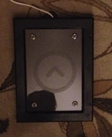
I had decided I wanted to side light the top layer of acrylic and etch the artwork in to it rather than use printed artwork. I thought it would look more interesting, and it was a good excuse to play with the laser at the maker space.
The build
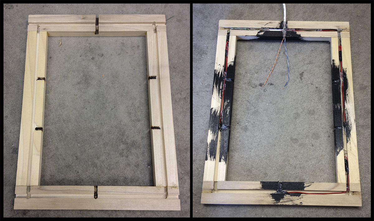
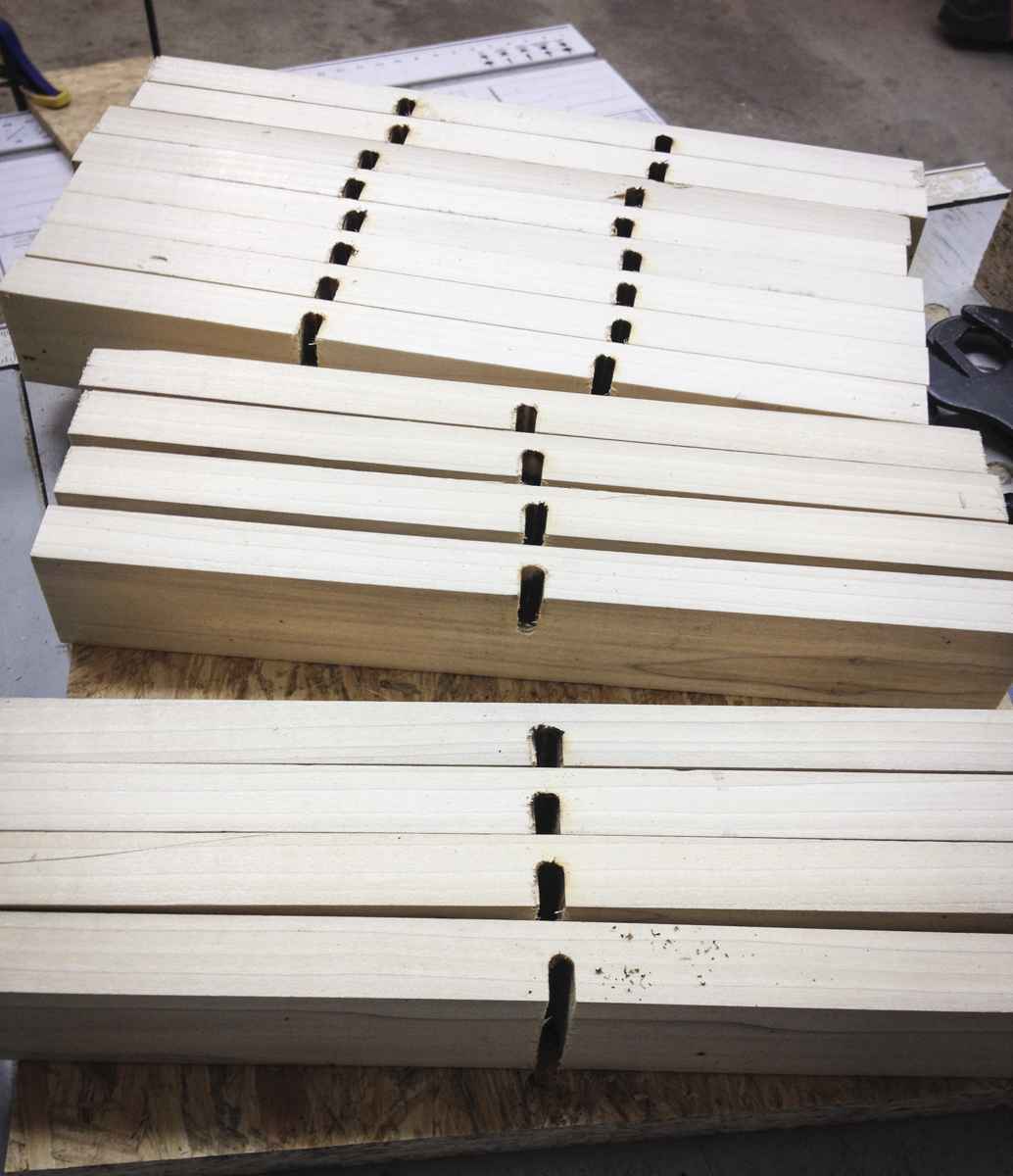 I started out with the side trim frame parts for the pads. To side light the acrylic, I routed LED channels and wire chases out of the frame pieces. I knew I needed the LEDs to shine in to the sides of the top sheet of acrylic, so I measured the height of two pieces of 1/8 inch acrylic and a well smashed chunk of weatherstripping to estimate the optimal hight of the LEDs. I set my router depth based on what I came up with. I glued and brad nailed the frames together, soldered everything up, and used hot glue to hold the LEDs and wire in place. I used a different color for each pad, just for some variety. As you can see I pre-painted the frame edges where the LEDs were mounted so I wouldn’t have to try to keep paint off the LEDs while doing it later. For the top frame piece, I routed a slot all the way out the top for the stomp pad’s cable to go through.
I used ethernet wire for the main cables for these because I have a ton of it and its cheap. I used two pairs to power the LEDs and ran two pairs out to connect to the pad contacts.
Once I was sure the LEDs all worked, I glued and clamped the frames down to bases I made from some nice sturdy 3/4″ OSB subfloor scraps I had laying around.
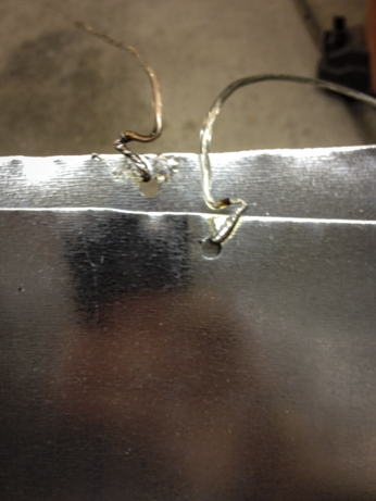 Next, I cut a bunch of good large foot sized rectangles of flashing from a roll I picked up at Lowes. I drilled holes in them at the top center and wrapped and soldered some wire pigtails to each. I wrapped it around to get a good mechanical connection. I pushed the wires off to opposite sides for the top and bottom sheet so that they wouldn’t interfere with each other or short out when the sheets were squished down close together in the final assembly.
I cut two sheets of acrylic for each pad and checked fit. The top sheets I handed off to a friend at the maker space to be etched. The bottom sheets got the sheet metal glued on one side, and a coat of flat black spray paint on the other. The paint was to keep the guts of the pad from showing through and provide a nice black background for the etched upper pieces. I certainly could have used black acrylic for the bottom sheets and skipped the painting, but I didn’t have any on hand.
 I got the other pieces of sheet metal glued down on the bases and installed the weather stripping around the perimeters of the switch well. While I waited to get the etched top sheets back I ran the pads through the router again to chamfer the edges. I hoped it would make them a little harder to trip on. Once I had the top sheets back I stacked everything up on the drill press and drilled screw holes down through the acrylic with a plastic bit. I planned to use some hardened hardy backer screws to make sure they wouldn’t snap off when stomped. I made the holes a little too big for them so that I could sleeve them with some silicone fish tank tubing to protect the acrylic.
 I soldered the pigtails from the metal sheets to the stomp pad cables, gave all the wood a coat of nice hard shiny black enamel, and screwed everything together! To test, I ran power for the LEDs in series with the stomp pad switch so that I could see when the contacts were making. I adjusted the screws up or down to get a nice even response from anything over about 20lbs, anywhere on the pad.
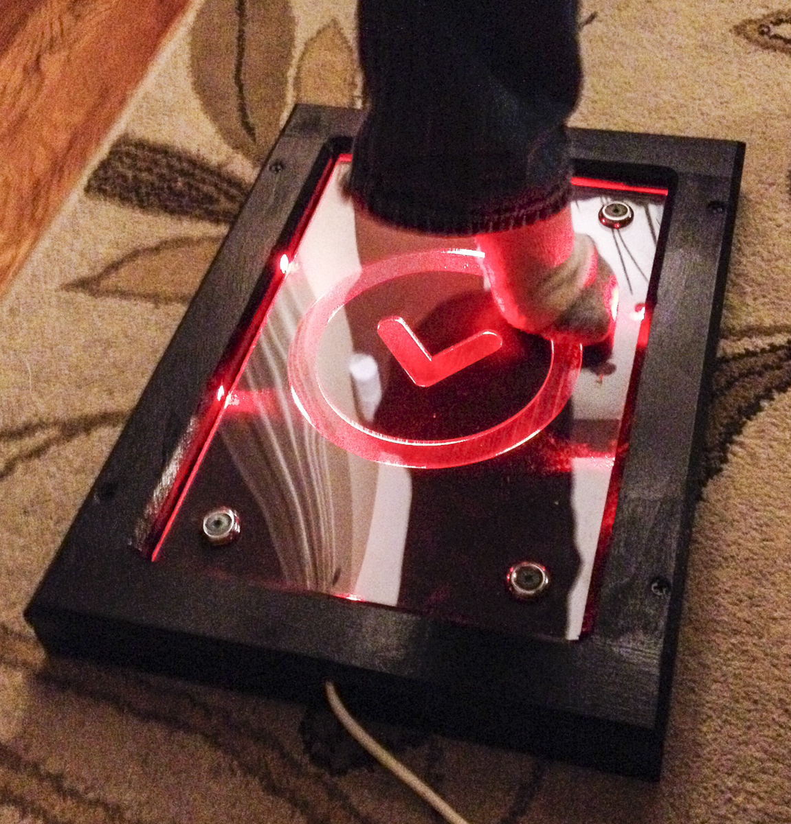 I turned the whole rig over to my in house durability assurance specialist. He did his thing and had a blast and everything seemed to work perfectly!
The pads now go off to meet up with the game portion of the build. One of the guys at the maker space is setting snake up to run on a Pi, and we’ll project the whole thing on the wall at the maker faire. I’ll try to get good pictures and update the post with some results!
Leave a Reply